What’s new in MyHDL 0.8
Modular bit vector types
Rationale
In hardware modeling, there is often a need for the elegant
modeling of wrap-around behavior. intbv instances
don’t provide this automatically, because they assert
that any assigned value is within the bound constraints.
Therefore, one has currently has to use other language
features for wrap-around modeling.
Often, this is straightforward. For example, the wrap-around condition for a counter is often decoded explicitly, as it is needed for other purposes. Also, the modulo operator provides an elegant one-liner in most scenarios.
However, in some important cases the current solution is not satisfactory. For example, we would like to describe a free running counter using a variable and augmented assignment as follows:
count += 1
This is not possible with the intbv type, as we
cannot add the modulo behavior to this description. A similar
problem exist of for a left shift as follows:
shifter <<= 4
These operations can only supported directly with a new type. For these reasons, it was felt that this would be a useful addition to MyHDL.
Solution
The proposed solution is to borrow the idea behind Ada modular types. These are natural integer types with wrap-around behaviour.
The wrap-around behavior of modular types is based on the sound mathematical concept of modulo arithmetic. Therefore, the modulus is not limited to powers of 2.
Ada’s modular type is called mod. In MyHDL, we want also
want to give it “bit-vector” support, like intbv. Therefore,
proposed MyHDL type is called modbv.
Implementation
modbv is implemented as a subclass of intbv.
The two classes have an identical interface and work together
in a straightforward way for arithmetic operations.
The only difference is how the bounds are handled: out-of-bound values
result in an error with intbv, and in wrap-around with
modbv. The Wrap-around behavior would be defined as follows, with val
denoting the current value and min/max the bounds:
val = (val - min) % (max - min) + min
Interface
-
class
modbv([val=0] [, min=None] [, max=None]) The
modbvclass implements modular bit vector types.It is implemented as a subclass of
intbvand supports the same parameters and operators. The difference is in the handling of the min and max boundaries. Instead of throwing an exception when those constraints are exceeded, the value ofmodbvobjects wraps around according to the following formula:val = (val - min) % (max - min) + min
This formula is a generalization of modulo wrap-around behavior that is often useful when describing hardware system behavior.
Conversion
Full-range modbv objects are those where the max bound is
a power of 2, and the min bound is 0 or the negative of the max bound.
For these objects, conversion worked out-of-the-box because this
corresponds to the target types in Verilog and VHDL.
Currently, conversion is restricted to full-range modbv
objects. It may be possible to support conversion of the modulo
behavior of more general cases, but this requires more sophistication
in the converter. This may be considered in the future.
always_seq decorator
Rationale
In classical synthesizable RTL coding, the reset behavior is described explicitly. A typical template is as follows:
@always(clock.posedge, reset.negedge)
def seq():
    if reset == 0:
        <reset code>
    else:
        <functional code>
The reset behavior is described using a the top-level if-else structure with a number of assignments under the if. A significant piece of code at a prominent location is therefore dedicated to non-functional behavior.
Reset behavior coding is error-prone. For a proper gate-level implementation, most if not all registers should typically be reset. However, it is easy to forget some reset assignments. Such bugs are not necessarily easily detected during RTL or gate-level simulations.
In the template, the edge that asserts reset is in the sensitivity list. It is easy to forget this, and in that case the reset will not behave asynchronously as intended but synchronously. Note also that it is somewhat strange to specify an edge sensitivity when describing asynchronous behavior.
Solution
The proposed solution is to infer the reset structure automatically. The main idea is to use the initial values of signals as the specification of reset values. This is possible in MyHDL, because all objects are constructed with an initial value. The assumption is that the initial value also specifies the desired reset value.
The solution is implemented with two new MyHDL constructs. The first
one is a new decorator called always_seq. Using this
decorator, code with identical behavior as in the previous section can
be described as follows:
@always_seq(clock.posedge, reset=reset)
    <functional code>
The always_seq decorator takes two arguments: a clock edge
and a reset signal. It inspects the code to find the registers, and
uses the initial values to construct the reset behavior.
The second construct is a specialized signal subclass called
ResetSignal. It is used as follows:
reset = ResetSignal(1, active=0, async=True)
The ResetSignal constructor has three arguments: the initial value as usual, an active argument with the active level, and an async argument that specifies whether the reset style is asynchronous or synchronous.
The proposed solution has some very desirable features.
Explicit reset behavior coding is no longer necessary. Code reviewers are thus no longer distracted by non-functional code. It is sufficient to check the initial values to verify whether the reset value is correctly specified. Moreover, one indentation level is saved for functional coding.
Even more importantly, the reset structure is correct by construction. All registers are automatically included in the reset behavior, and the sensitivity list is automatically correct according to the reset style.
Traditionally, the reset behavior is spread out over all sequential
processes. Therefore, it has to be debugged by investigating all those
processes. Even worse, if a change in style or active level is
required, all processes are affected. In contrast, with the proposed
technique all reset features are specified at single location in the
ResetSignal constructor. Changes are trivial. For example, to
change to an active high synchronous reset one merely has to change
the constructor as follows:
reset = ResetSignal(1, active=1, async=False)
Occasionally, it is useful to have registers without reset at
all. The proposed technique is also useful in that case. In
particular, the always_seq decorator accepts None as the reset
argument:
@always_seq(clock.posedge, reset=None)
A reviewer will have no doubt what the intention is. In contrast, in the case of a traditional always block, the reviewer may think that the designer has delayed the detailed reset coding for later and then forgotten about it.
Interface
-
always_seq(edge, reset) The
always_seqdecorator is used to describe sequential (clocked) logic.The edge parameter should be a clock edge (
clock.posedgeorclock.negedge). The reset parameter should aResetSignalobject.
-
class
ResetSignal(val, active, async) - This
Signalsubclass defines reset signals. val, active, and async are mandatory arguments. val is a boolean value that specifies the initial value, active is a boolean value that specifies the active level. async is a boolean value that specifies the reset style: asynchronous (True) or asynchronous (False).
Conversion
As modeling the reset behavior is a typical task in synthesizable RTL coding, the proposed technique is fully convertible to Verilog and VHDL.
Limitations
All registers in a process are reset
All registers in a process are automatically included in the reset behavior. If it is the intention that some registers should not be reset, those registers and the corresponding code should be factored out in a separate process.
Actually, this is not really a limitation but a feature. If some registers in a process are reset and others not, a synthesis tool may generate undesirable feedback loops that are active during the reset condition. This is not good practice and probably not the intention.
Register inferencing from variables is not supported
An important limitation is that the proposed technique is limited to
registers inferred from signals. Registers inferred from variables are
not supported, because such state variables cannot be described in
classic functions (in particular the functions required by MyHDL
decorators such as always_seq and always).
In fact, the reason is a Python2 limitation. Currently, to infer
registers from variables, one has to use the instance decorator and
declare the state variables outside an infinite while True loop.
In Python3, this limitation can be lifted with the introduction of the
nonlocal declaration. This will make it possible for functions to
modify variables in the enclosing scope. It should be possible to
adapt the always_seq and always decorators to support such
variables.
Other improvements
Conversion of top-level class methods
Often it is desirable to embed an HDL module description in a class. Previous versions would only convert a class method if it was not the top-level. This release adds the conversion of top-level class methods.
Example
class DFilter(object):
    def __init__(self,delay_length=3,fs=1):
        <init code>
    def nulls(self):
        <support method code>
    def m_top(self,clock,reset,x,y):
        <myhdl module code>

clock = Signal(bool(0))
reset = ResetSignal(0,active=0,async=True)
x = Signal(intbv(0, min=-8, max=8))
y = Signal(intbv(0, min=-64, max=64))

filt = DFilter()
toVerilog(filt.m_top,clock,reset,x,y)
toVHDL(filt.m_top,clock,reset,x,y)
Tracing lists of signals
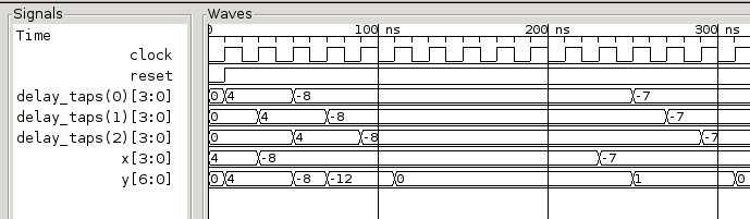
Tracing lists of signals is now supported. Contributed by Frederik Teichtert, http://teichert-ing.de . The following shows how the list of signals are displayed in a waveform viewer
delay_taps = [Signal(intbv(0,min=-8,max=8)) for ii in range(3)]
library attribute for toVHDL
toVHDL now has a library function that
can be used to set the library name in the
VHDL output. The assigned value should be a string.
The default library is “work”.
timescale attribute for traceSignals
traceSignals now has a timescale attribute
that can be used to set the timescale
in the VCD output. The assigned value should be a string.
The default timescale is “1ns”.
Acknowledgments
Several people have contributed to MyHDL 0.8 by giving feedback, making suggestions, fixing bugs and implementing features. In particular, I would like to thank Christopher Felton and Frederik Teichert.
I would also like to thank Easics for the opportunity to use MyHDL in industrial projects.